Introduction
Over the last few years LEDs are becoming much more common at Burning Man. This is generally a good thing, as it means we are likely to (hopefully) see fewer glow sticks left lying around the desert. Unfortunately, most of the LEDs on the playa tend to be of the annoying blinky variety. I have decided to share my design for the fading LED circuit, but also use it to teach a short introduction to analog circuits. In the end you will be able to make something like Franziska’s hat which uses my circuit to illuminate the diffusing tubes she has sewn into her hat.
Parts
To complete this tutorial I recommend the following parts:
- 1 Breadboard - I recommend 60 columns with rails running across the top and bottom because it gives you room to work, but smaller breadboards will work as well. You can obtain an inexpensive breadboard from Jameco.
- 1 9V battery - All the designs I make will run on 9V. They can be adapted, but 9V batteries are common.
- 1 9V battery snap
- 4 100 kOhm resistors
- 1 47 kOhm resistor
- 1 470 Ohm resistor
- 1 22 kOhm resistor
- 2 to 10 220 Ohm resistors
- 1 100 uF capacitor
- 1 LM358AN General Purpose Dual Op Amp
- 1 2N3904 NPN Transistor - Any general purpose NPN transistor which can deliver 200 mA max should do.
- 1 2N3906 PNP Transistor - Any general purpose PNP transistor which can deliver 200 mA should do here as well.
- 4 to 20 LEDs - I’ll be using red LEDs for this project, but other colors will work as well (reds tend to be cheapest). We’re looking for 20-30 mA forward current and around 2-3 V forward voltage drop.
- 1 Digital Multimeter - Although not strictly necessary to follow this tutorial it is a must to see exactly what’s happening in your circuit. Fluke meters are the standard, but if you’re like me you don’t yet have \$200 to spend on a meter, so get an inexpensive one.
Lighting Your LED
Our first circuit is very straightfoward, but it also will show us some basic principles for circuits. We will create a simple circuit to illuminate our LED using the battery and one resistor to regulate the current. I will be creating diagrams of these circuits using standard electronic symbols which you can find online. I will be drawing circuit diagrams using CircuitLab and simulating some of them using the circuit simulator applet.
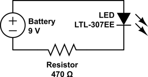
In the circuit above we connect the positive lead of the battery to the LED anode (the longer leg). The LED cathode (shorter leg) is connected to a 470 Ohm resistor, and the other end of that resistor is connected to the negative lead of the battery.
We can use the breadboard to help make our connections. The breadboard has a bunch of holes in it, and in the wholes are conductors that connect them to other holes in a specific pattern. Conductors run vertically along columns in the middle of the breadboard, with a gap in the center row (here the breadboard often has a groove). Along the top and bottom are 1 or 2 rows in which the conductors are placed horizontally. These are often used to provide power and are called power rails. The connections are shown in the diagram below.

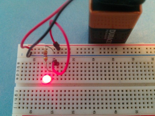
The connected circuit should look like the image below, and if the connections are right the LED should light up.
So how do we hook up our multimeter to make measurements? We will want to measure two properties in most circuits: voltage and current. Each one is measured quite differently.
Measuring Voltage
Voltage is not an absolute quantity. When one measures voltage, one is measuring an electric potential difference between two points in a circuit. For example, when we say that a battery is a 9 Volt battery, that means that the potential difference between the + terminal and the - terminal is 9 Volts. Often we measure relative to a specific reference point on the circuit, which we refer to as ground, however when measuring voltage with a meter you will have to choose the two locations on your circuit to measure and the voltage you read will be the difference in electric potential between those two points.
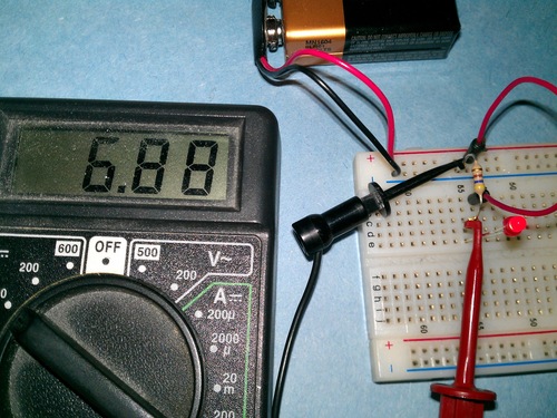
In my circuit, I want to see the voltage across the resistor. To do this I hook up the leads to each side of the resistor. I leave the rest of the circuit alone. I know that the side of the resistor closer to the - terminal of the battery will have a lower potential, so I connect my black lead there (The COM or V- port of the multimeter). I connect my red lead to the other side and see that the voltage across the resistor is 6.88 Volts.
I am also going to measure the current through the resistor (and through the circuit in general) but before I do that, let’s stop and figure out what it should be using Ohm’s Law. Ohm’s law states that the voltage across a resistor (\(V\)) is proportional to the current across the resistor (\(I\)) and that the constant of proportionality is the resistance (\(R\)) of the resistor, or
Since we know we have a 470 \(\Omega\)) resistor, we can calculate that the current through the resistor should be
Measuring Current
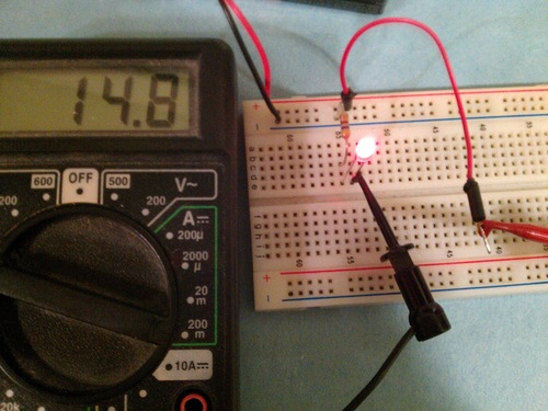
Current is an absolute quantity. It is a measure of the flow of charge past a point in the circuit per unit time. In order to measure this flow, we must pass it in its entirety through our multimeter. The way we do this is by breaking the circuit and inserting our multimeter into it. To measure the current through this circuit I will break the loop connecting the battery, to the LED, to the resistor and back to the battery and insert the multimeter in between two of the components. I do this by disconnecting the connecting wire between the +9V power rail and the LED. I set my multimeter to read current, and I get the situation below. Notice that the red wire runs only to the multimeter now, and that the current flows out the multimeter through the black wire into the LED.
Why the Resistor?
Why do I include a resistor at all in this circuit? And why measure the voltage and current? It turns out an LED has a consistant voltage drop across it regardless of voltage (for this red LED it is 1.8 V) and the resistor is there to regulate the current running through the remaining voltage drop to the negative battery lead. This in turn regulates the current passing through the LED, which is the same as the current running through the resistor.
How do you select a resistor to regulate the current through an LED? You can use the relationship
where (\(R\)) is the resistance, (\(V_b\)) is the voltage of the battery, (\(V_d\)) is the voltage across the LED, and (\(I\)) is the desired current through the LED. Real resistors only come in certain resistance values, so you will likely have to select a resistance slightly larger than the resistance which allows for the maximum rated current of the LED.
So far we’ve learned how to make a basic circuit which illuminates an LED, and how to hook up a multimeter. In part 2 I’ll introduct the capacitor which will be a key component is getting the brightness of our LED to vary slowly as well as a key component in any time varying circuitry.